- Illustrator User Guide
- Get to know Illustrator
- Introduction to Illustrator
- Workspace
- Workspace basics
- Create documents
- Learn faster with the Illustrator Discover panel
- Accelerate workflows using the Contextual Task Bar
- Toolbar
- Default keyboard shortcuts
- Customize keyboard shortcuts
- Introduction to artboards
- Manage artboards
- Customize the workspace
- Properties panel
- Set preferences
- Touch Workspace
- Microsoft Surface Dial support in Illustrator
- Undo edits and manage design history
- Rotate view
- Rulers, grids, and guides
- Accessibility in Illustrator
- View artwork
- Use the Touch Bar with Illustrator
- Files and templates
- Tools in Illustrator
- Tools at a glance
- Select tools
- Navigate tools
- Paint tools
- Text tools
- Draw tools
- Modify tools
- Generative AI (not available in mainland China)
- Quick actions
- Illustrator on the iPad
- Introduction to Illustrator on the iPad
- Workspace
- Documents
- Select and arrange objects
- Drawing
- Type
- Work with images
- Color
- Cloud documents
- Basics
- Troubleshooting
- Add and edit content
- Drawing
- Drawing basics
- Edit paths
- Draw pixel-perfect art
- Draw with the Pen, Curvature, or Pencil tool
- Draw simple lines and shapes
- Draw rectangular and polar grids
- Draw and edit flares
- Trace images
- Simplify a path
- Symbolism tools and symbol sets
- Adjust path segments
- Design a flower in 5 easy steps
- Create and edit a perspective grid
- Draw and modify objects on a perspective grid
- Use objects as symbols for repeat use
- Draw pixel-aligned paths for web workflows
- Measurement
- 3D objects and materials
- Color
- Painting
- Select and arrange objects
- Select objects
- Layers
- Expand, group, and ungroup objects
- Move, align, and distribute objects
- Align, arrange, and move objects on a path
- Snap objects to glyph
- Snap objects to Japanese glyph
- Stack objects
- Lock, hide, and delete objects
- Copy and duplicate objects
- Rotate and reflect objects
- Intertwine objects
- Create realistic mockups
- Reshape objects
- Crop images
- Transform objects
- Combine objects
- Cut, divide, and trim objects
- Puppet Warp
- Scale, shear, and distort objects
- Blend objects
- Reshape using envelopes
- Reshape objects with effects
- Build new shapes with Shaper and Shape Builder tools
- Work with Live Corners
- Enhanced reshape workflows with touch support
- Edit clipping masks
- Live shapes
- Create shapes using the Shape Builder tool
- Global editing
- Type
- Add text and work with type objects
- Add basic formatting to text
- FAQs on fonts in Illustrator
- Fonts and typography
- Create type on a path
- Create bulleted and numbered lists
- Manage text area
- Add advanced formatting to text
- Format paragraphs
- Character and paragraph styles
- Special characters
- Tabs
- Scale and rotate type
- Line and character spacing
- Hyphenation and line breaks
- Spelling and language dictionaries
- Format Asian characters
- Arabic and Hebrew type
- Composers for Asian scripts
- Reflow Viewer
- Preview, add, or replace missing fonts
- Import and export text
- Identify the fonts used in images and outlined text
- Creative typography designs
- Create text designs with blend objects
- Create a text poster using Image Trace
- Create special effects
- Web graphics
- Drawing
- Import, export, and save
- Import
- Creative Cloud Libraries in Illustrator
- Save and export
- Printing
- Prepare for printing
- Printing
- Automate tasks
- Troubleshooting
- Fixed issues
- Known issues
- Crash issues
- Recover files after crash
- Repair damaged documents
- Safe mode
- File issues
- Supported file formats
- GPU device driver issues
- GPU performance issues
- Wacom device issues
- DLL file issues
- Memory issues
- Preferences file issues
- Font issues
- Printer issues
- Media issues
- Missing plugin issues
- Share crash report with Adobe
- Unable to apply effects in Illustrator
- Improve Illustrator performance
- Fixed issues
In Illustrator, you can create different types of graphs and customize them to suit your needs. Click and hold the Graph tool ( ) in the Tools panel to see all different types of graphs you can create.


Create graphs
|
|
|
-
Select a graph tool.
The Graph tool you use initially determines the type of graph Illustrator generates. For example, to create a column graph, select the Column Graph tool. However, you can easily change the type of graph later. For details, see Change graph type.
-
To define the dimensions of the graph, do one of the following:
Drag diagonally from the corner where you want the graph to begin to the opposite corner. Alt‑drag (Windows) or Option‑drag (macOS) to draw the graph from its center. Hold down Shift to constrain the graph to a square.
Click where you want to create the graph. Enter a width and height for the graph, and click OK.
Note: The dimensions you define are for the main body of the graph and do not encompass the graph’s labels and legend.
-
Enter data for the graph in the Graph Data window. For more details, see Enter graph data.
NoteGraph data must be arranged in a specific order, which varies by graph type.
-
Click the Apply button
 , or press the Enter key on the numeric keypad to create the graph.
Apply the values you've entered in the Graph Data window Apply the values you've entered in the Graph Data window The Graph Data window stays open until you close it. This allows you to easily switch between editing graph data and working on the artboard.
Enter graph data
You use the Graph Data window to enter the data for your graph. The Graph Data window appears automatically when you use a graph tool and stays open until you close it.


|
Callout |
Title |
Description |
|---|---|---|
|
A |
Entry text box |
Enter the data |
|
B |
Import data |
Import data saved as a text file |
|
C |
Transpose row/column |
Switch the columns and rows of data
|
|
D |
Switch x/y |
Switch the x and u axes of graphs
|
|
E |
Cell style |
Adjust the column width or decimal precision of cells
|
|
F |
Revert |
Revert the changes you've made in the graph data |
|
G |
Apply |
Apply the changes you've made in the graph data |
-
Display the Graph Data window for an existing graph: select the entire graph with the Selection tool, and then choose Object > Graph > Data.
-
Enter data in any of the following ways:
Select a cell in the worksheet, and enter the data in the text box at the top of the window. Press Tab to input the data and select the next cell in the same row; press Enter or Return to input the data and select the next cell in the same column; use the arrow keys to move from cell to cell; or simply click another cell to select it.
Copy data from a spreadsheet application such as Lotus® 1‑2‑3 or Microsoft Excel. In the Graph Data window, click the cell that will be the upper‑left cell of the data you paste and choose Edit > Paste.
Copy data from a spreadsheet and paste it in the Graph Data window Copy data from a spreadsheet and paste it in the Graph Data window Create a text file using a word-processing application. While entering your data, separate the data for each cell by a tab and the data for each row by a paragraph return. The data should only contain decimal points or decimal commas; otherwise, the data is not plotted. (For example, enter 732000, not 732,000.) In the Graph Data window, click the cell that will be the upper‑left cell of the data you import, click the Import Data button (
 ) , and select the text file.
Note- If you accidentally enter graph data backward (that is, in rows instead of columns, or vice versa), click the Transpose button (
 ) to switch the columns and rows of data.
 - To switch the x and y axes of scatter graphs, click the Switch X/Y button (
 ) .
) .
-
Click the Apply button
 or press the Enter key on the numeric keypad to regenerate the graph.
Use graph labels and data sets
Labels are words or numbers that describe two things:
- The sets of data you want to compare
- The categories across which you want to compare them

A. Data set labels B. Blank cell C. Category labels

|
Callout |
Title |
Description |
|---|---|---|
|
A |
Data set labels |
Enter labels for the different sets of data in the top row of cells. These labels appear in the legend. |
|
B |
Blank cell |
To generate a legend for the graph, leave the upper-left cell blank. |
|
C |
Category |
Enter labels for the categories in the left column of cells. |
Enter labels
-
For column, stacked column, bar, stacked bar, line, area, and radar graphs, enter labels in the worksheet as follows:
If you want Illustrator to generate a legend for the graph, delete the contents of the upper‑left cell and leave the cell blank.
Enter labels for the different sets of data in the top row of cells. These labels will appear in the legend. If you don’t want Illustrator to generate a legend, don’t enter data‑set labels.
Enter labels for the categories in the left column of cells. Categories are often units of time, such as days, months, or years. These labels appear along either the horizontal axis or vertical axis of the graph, with the exception of radar graphs, for which each label results in a separate axis.
To create labels consisting only of numbers, enclose the numbers in straight quotation marks. For example, enter "2013" to use the year 2013 as a label.
Create labels consisting of only numbers Create labels consisting of only numbers To create line breaks in labels, use the vertical bar key to separate lines. For example, type Total|Sales|2013 to produce the following graph label:
Total
Sales
2013
Create line breaks in labels Create line breaks in labels
Enter data sets
After you enter the labels for your graph, you’re ready to enter each set of data under the appropriate column.
The height of the column corresponds to the amount being compared. You can combine positive and negative values; negative values appear as columns extending below the horizontal axis.


The height of the column corresponds to the amount being compared. For stacked column graphs, numbers must be all positive or all negative.


The length of the bar corresponds to the amount being compared. You can combine positive and negative values. Negative values appear as columns extending below the horizontal axis.


The length of the bar corresponds to the amount being compared. For stacked bar graphs, numbers must be all positive or all negative.


Each column of data corresponds to one line in the line graph. You can combine positive and negative values in a line graph.


Values must be all positive or all negative. Each row of data entered corresponds to a filled area on the area graph. Area graphs add each column’s values to the previous column’s totals. Therefore, even if area graphs and line graphs contain the same data, they appear substantially different.


A scatter graph differs from the other kinds of graphs in that both axes measure values; there are no categories.
- Enter dataset labels in every other cell along the top row of the worksheet, starting with the first cell. These labels will appear in the legend.
- Enter yaxis data in the first column and xaxis data in the second column.
Note: Disable the option Connect Data Points to remove connecting lines.


You can organize data sets for pie graphs similarly to other graphs. However, each row of data in the worksheet generates a separate graph.
- Enter dataset labels as for column, stacked column, bar, stacked bar, line, area, and radar graphs. Enter category labels if you want to generate graph names.
- To create a single pie graph, plot only one row of data, either all positive or all negative values.


- To create multiple pie graphs, plot additional rows of data, either all positive or all negative values. By default, the size of the individual pie graphs is proportional to the total of each graph’s data.


Each number is plotted on an axis and connected to the others in the same axis to create a “web.” You can combine positive and negative values in a radar graph.


Adjust column width or decimal digits
To view more or fewer digits in a column, adjust the column width. This change has no effect on the width of columns in the graph.
Adjust the width of columns
-
Do one of the following:
Click the Cell Style button (
 ) and enter a value between 0 and 20 in the Column Width text box.
Position the pointer at the edge of the column you want to adjust. The pointer changes to a double arrow
 . Then drag the handle to the desired position.

Adjust the Column Width text box to view fewer digits in a column

Adjust the Column Width text box to view more digits in a column
Adjust the decimal precision for cells
-
Click the Cell Style button (
 ) and enter a value between 0 and 10 in the Number of Decimals text box.
With the default value of 4 decimals, the number 2000 entered in a cell appears in the Graph Data window box as 2000.00

With the default value of 2 decimals, the number 2000 entered in a cell appears in the Graph Data window box as 2000.0000
Combine different graph types
You can combine different graph types in one graph. For example, you may want one set of data to appear as a column graph and other sets of data to appear as a line graph. You can combine any type of graph with any other, with the exception of scatter graphs. Scatter graphs cannot be combined with any other graph type.


-
Select the Group Selection tool (
 ).
). -
Click the legend for the data whose graph type you want to change.
-
Without moving the Group Selection tool pointer from the legend, click again. All of the columns grouped with the legend are selected.
-
Do one of the following:
- Choose Object > Graph > Type.
- Double-click the Graph tool in the Tools panel.
-
Select the graph type and options you want.Note
- If a graph uses more than one graph type, you may want one set of data along the right axis and the other set of data along the left axis. In this way, each axis measures different data.
- If you use stacked column graphs with other graph types, be sure to use the same axis for all sets of data that are represented by stacked column graphs. If some sets of data use the right axis while others use the left, the column heights may be misleading or may overlap.
Format and customize graphs
You can format graphs in a variety of ways. For example, you can change the appearance and position of the graph’s axes, add drop shadows, and move the legend.
Moreover, you can change the colors of shading, typeface, and typestyle; move, reflect, shear, rotate, or scale any or all parts of the graph; and customize column and marker designs. You can apply transparency, gradients, blends, brush strokes, graphic styles, and other effects to graphs. Always apply such customizations in the end, because regenerating the graph removes them.
A graph is a grouped object that is related to its data. Ungrouping the graph may disable you to make the desired changes. To edit a graph, select the parts you want to edit without ungrouping the graph, using either the Direct Selection tool ( ) or the Group Selection tool (
 ).
).
Elements of a graph are related to each other. The entire graph with its legends is one group. All the sets of data are a subgroup of the graph; in turn, each set of data with its legend box is a subgroup of all the sets of data. Each value is a subgroup of its set of data, and so on. Avoid ungrouping or regrouping objects that are within the graph.
-
Select the Group Selection tool (
 ).
). -
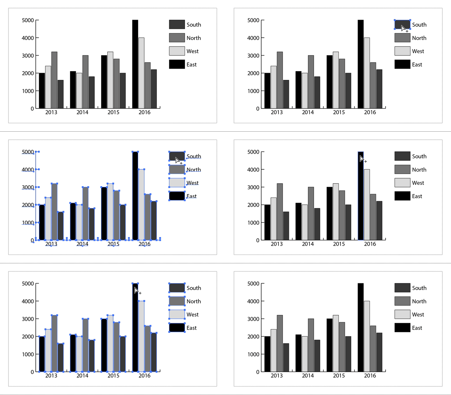
Click the legend of the columns you want to select.
-
Without moving the Group Selection tool pointer from the legend, click again. All of the columns grouped with the legend are selected.
You can also select a group by clicking one of its parts, clicking again to select columns grouped with it, and clicking a third time to select the legend. Each click adds another layer of grouped objects to the selection, beginning with the next group up in the hierarchy. You can click as many times as the number of groups to add to a selection.

-
To deselect part of a selected group, select the Direct Selection tool (
 ) and Shift‑click the object.
-
Select the graph you've created using the Selection tool (
 ).
). -
Do one of the following:
- Choose Object > Transform > Scale or double-click the Scale tool (
 ) and specify the desired values in the Scale dialog box.
- Select the Scale tool (
 ) and drag anywhere in the document window until the object is the desired size.
For details, see Scale, shear, and distort objects.
- Choose Object > Transform > Scale or double-click the Scale tool (
-
Select a graph with the Selection tool (
 ).
). -
Do one of the following:
- Click Graph Options in the Properties panel.
- Choose Object > Graph > Type.
- Double-click the Graph tool in the Tools panel.
-
In the Graph Type dialog box, click the button that corresponds to the desired graph type, and click OK.
NoteOnce graph objects are painted with gradients, changing graph types can cause unexpected results. To prevent undesirable results, either do not apply gradients until the graph is finished, or use the Direct Selection tool to select gradient-painted objects and paint those objects with a process color; then reapply the original gradients.
With the exception of pie graphs, all graphs have a value axis which displays the unit of measurement for the graph. You can choose to display the value axis on one side or both sides of the graph. Bar, stacked bar, column, stacked column, line, and area graphs also have a category axis which defines the categories of data in the graph.
You can control how many tick marks appear on each axis, change the length of tick marks, and add a prefix and suffix to numbers on the axis.
-
Select the graph with the Selection tool (
 ).
). -
Do one of the following:
- Click Graph Options in the Properties panel.
- Choose Object > Graph > Type.
- Double-click the Graph tool in the Tools panel.
-
To change the position of the value axis, select an option from the Value Axis menu.
-
To format tick marks and labels, select an axis from the pop‑up menu at the top of the dialog box, and set the following options:
Tick Values
Determines the placement of tick marks on value axes, left axes, right axes, bottom axes, or top axes. Select Override Calculated Values to manually calculate the placement of tick marks. Either accept the values set when you created the graph or enter a minimum value, a maximum value, and the number of divisions between labels.
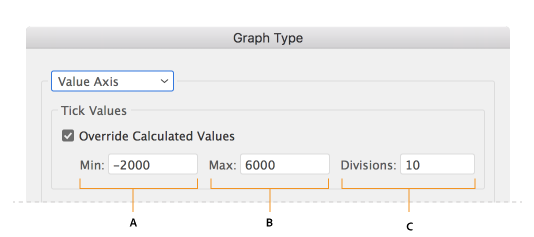
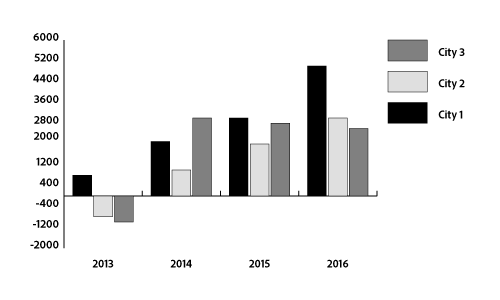
Example: Enter a minimum value, a maximum value, and the number of divisions between labels
Example: To determine the placement of tick marks, specify the Tick Values.
Tick Marks
Determines the length of tick marks and number of tick marks per division. For category axes, select Draw Tick Marks Between Labels to draw tick marks on either side of the labels or columns, or deselect the option to center tick marks over the labels or columns.
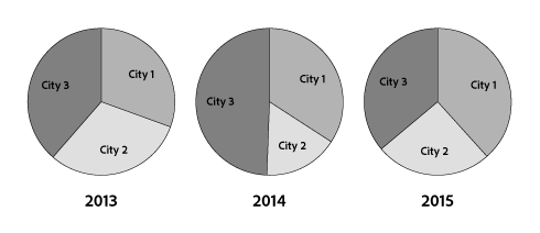
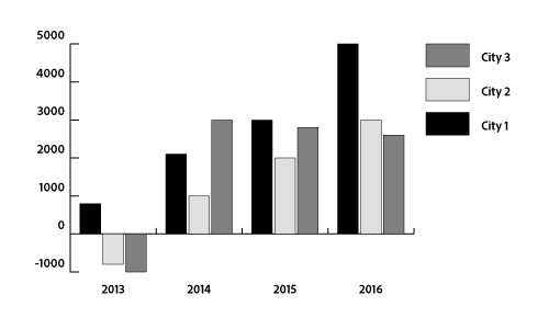
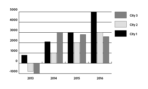
Example: Select None as the length of tick marks
Example: Select Short as the length of tick marks
Example: Select Fyll Width as the length of tick marks
Add Labels
Specifies a prefix and suffix for numbers on value axes, left axes, right axes, bottom axes, or top axes. For example, you can add a dollar sign or percent sign to axis numbers.
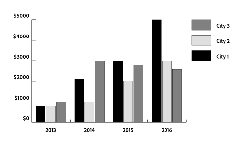
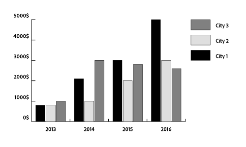
Example: Adding a dollar sign as a prefix to the numbers on the left axis
Example: Adding a dollar sign as a suffix to the numbers on the left axis
If your graph has a value axis on both sides, you can assign a different set of data to each axis. This causes Illustrator to generate a different scale for each axis. This technique is especially useful when you combine different graph types in the same graph.
-
Select the Group Selection tool (
 ).
). -
Click the legend for the data set you want to assign to the axis.
-
Without moving the Group Selection tool pointer from the legend, click again. All of the columns grouped with the legend are selected.
-
Do one of the following:
- Click Graph Options in the Properties panel.
- Choose Object > Graph > Type.
- Double-click the Graph tool in the Tools panel.
-
From the Value Axis pop‑up menu, select the axis to which you want to assign the data.
-
Click OK.
For column, stacked column, bar, and stacked bar graphs, you can adjust the amount of space between each column or bar in the graph. You can also adjust the amount of space between the categories, or clusters, of data in the graph. For line, scatter, and radar graphs, you can adjust the appearance of lines and data points.
-
Select the graph with the Selection tool (
 ).
). -
Do one of the following:
- Click Graph Options in the Properties panel.
- Choose Object > Graph > Type.
- Double-click the Graph tool in the Tools panel.
-
To adjust the space between columns and bars in a column, stacked column, bar, or stacked bar graph, enter a value between 1% and 1000% in the Column Width, Bar Width, or Cluster Width text box.
A value greater than 100% causes the columns, bars, or clusters to overlap one another. A value less than 100% leaves space between the columns, bars, or clusters. A value of 100% moves the columns, bars, or clusters flush against each other.
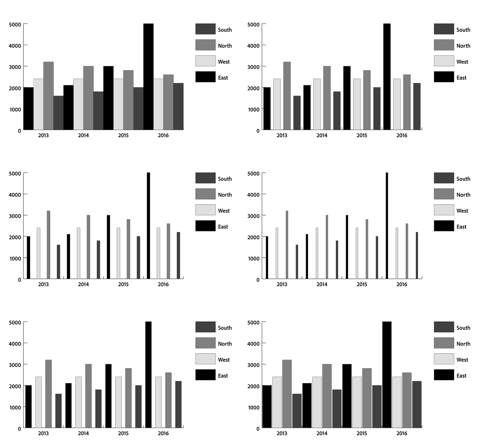
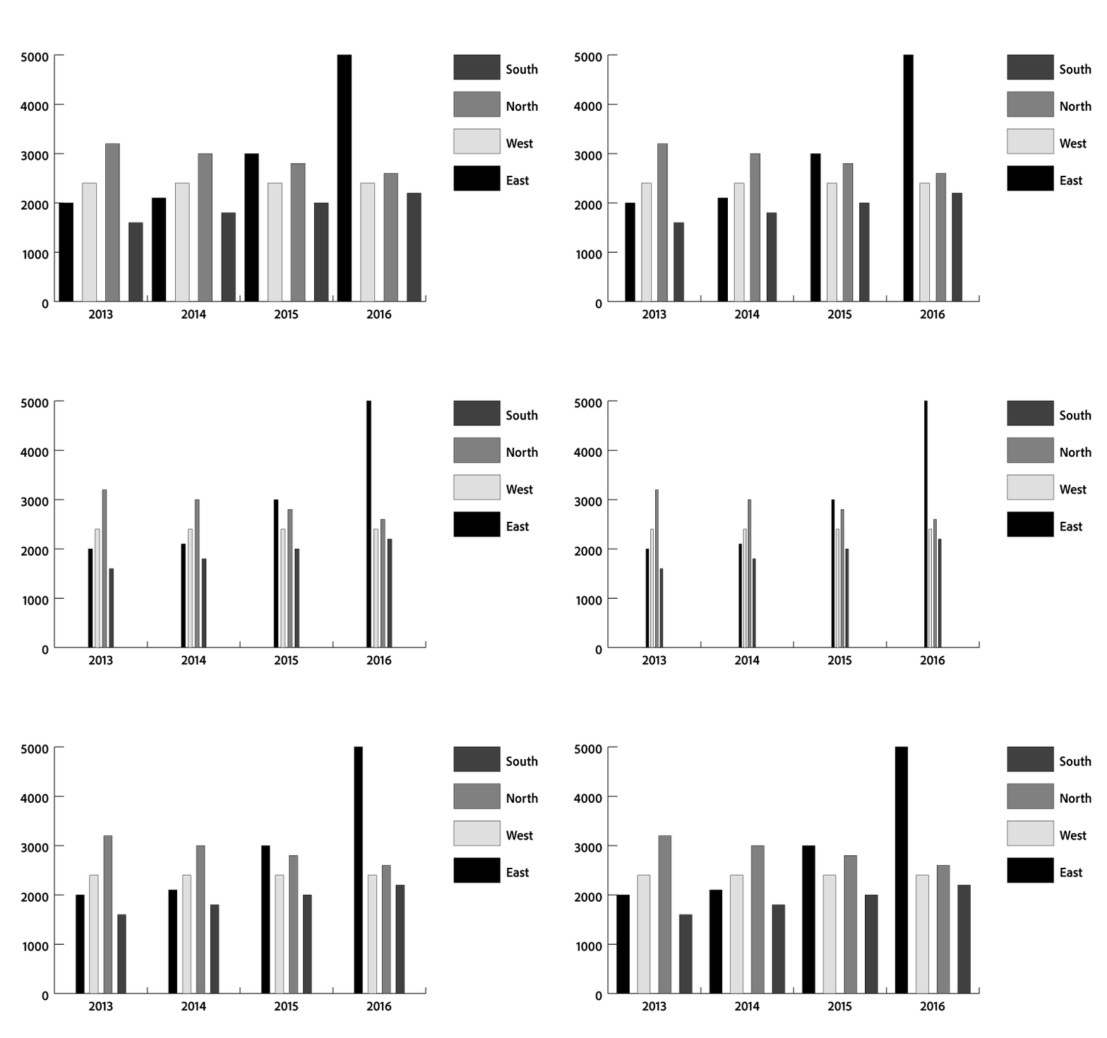
Example: Adjusting the cluster width
Example: Adjusting the column width
-
To adjust lines and data points in a line, scatter, and radar graph, set the following options:
- Mark Data Points: Places square markers at each data point.
- Connect Data Points: Draws lines that make it easier to see relationships among data.
- Edge‑to‑Edge Lines: Draws lines that extend across the graph, from left to right along the horizontal (x) axis. This option is not available for scatter graphs.
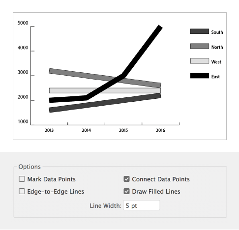
- Draw Filled Lines: Creates a wider line according to the value you enter in the Line Width text box, and which fills the line with paint according to the specifications for that series of data. This option becomes available when you select Connect Data Points.
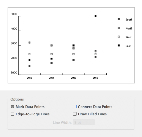
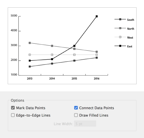
Example: Mark data points in a scatter graph
Example: Mark and connect data points in a scatter graph
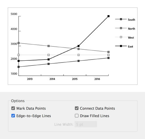
Example: Extend lines edge to edge across the horizontal axis
Example: Draw filled lines and adjusti its width
-
To change how columns, bars, and lines overlap, set the following options:
First Row In Front: Controls how the categories, or clusters, of data in a graph overlap when the Cluster Width is greater than 100%. This option is the most useful when working with column and bar graphs.
First Column In Front: Places the column, bar, or line that corresponds to the first column of data in the Graph Data window on top. This option also determines which column is on top for column and stacked column graphs with a Column Width greater than 100% and for bar and stacked bar graphs with a Bar Width greater than 100%.
NoteAlways select First Column In Front for area graphs. Some areas may not appear if you don't select this option.
You can change the placement of the legend and how wedges are sorted in pie graphs. You can also specify how you want to display multiple pie graphs.
-
Select the graph with the Selection tool (
 ).
). -
Do one of the following:
- Click Graph Options in the Properties panel.
- Choose Object > Graph > Type.
- Double-click the Graph tool in the Tools panel.
-
Do any of the following:
- To change the placement of the legend, select one of the following options for Legend:
- No Legend: Omits legends entirely.
- Standard Legend: Places column labels outside the graph; this is the default. Use this option when you combine pie graphs with other kinds of graphs.
- Legends In Wedges: Inserts labels into the corresponding wedges.
Change the placement of the legend A. Standard Legend B. Legends In Wedges C. No Legend
Change the placement of the legend - To specify how multiple pie graphs are displayed, select one of the following options for Position:
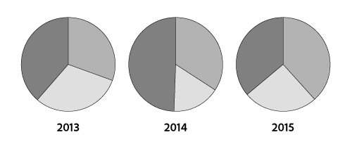
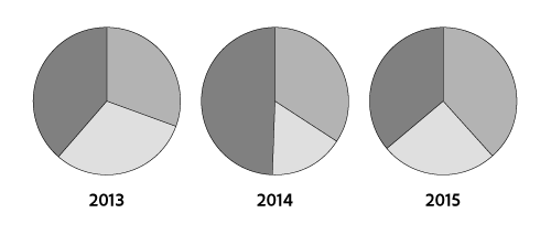
Ratio: Sizes the graphs proportionally.
Even: Makes all the pie graphs the same diameter.
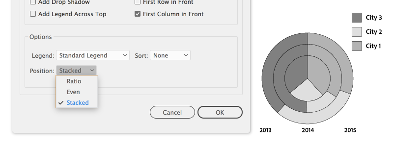
Stacked: Stacks each pie graph on top of the other, and each graph is sized proportionally to each other.
- To specify how wedges are sorted, select one of the following options for Sort:
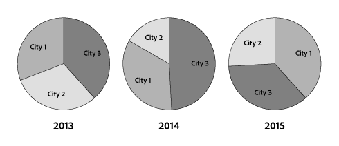
All: Sorts the wedges of the selected pie graphs from largest to smallest value proceeding clockwise from the top of the pie graph.
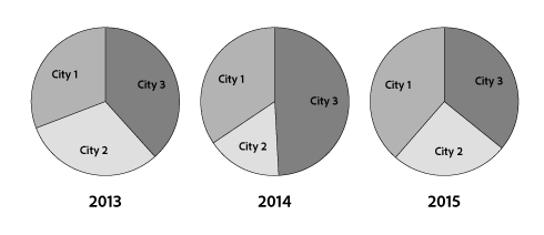
First: Sorts the wedges of the selected pie graphs so that the largest value in the first graph will be placed in the first wedge, and the rest will sort from largest to smallest. All other graphs will follow the order of the wedges in the first graph.

None: Sorts the wedges of the selected pie graphs in the order in which you entered values proceeding clockwise from the top of the graphs.
Tip: Percentages and legends are painted black by default. If a pie wedge with a dark background obscures a legend, repaint the dark background. Use the Group Selection tool to select the dark pie wedges, and paint the wedges using the Color panel or Swatches panel. - To change the placement of the legend, select one of the following options for Legend:
By default, the legend is displayed to the right of the graph. However, you can choose to display it horizontally across the top of the graph.
-
Select a graph with the Selection tool (
 ).
). -
Do one of the following:
- Click Graph Options in the Properties panel.
- Choose Object > Graph > Type.
- Double-click the Graph tool in the Tools panel.
-
In the Graph Type dialog box, select Add Legend Across Top, and click OK.
Illustrator uses a default font and font size when generating text for the graph’s labels and legend. However, you can easily change the formatting of type to add visual interest to your graph.
-
Select the Group Selection tool (
 ).
). -
Click once to select the baseline of the type you want to change; click twice to select all of the type.
-
Change the type attributes as desired.
You can apply drop shadows behind the columns, bars, or lines in a graph, and to entire pie graphs.
-
Select a graph with the Selection tool (
 ).
). -
Do one of the following:
- Click Graph Options in the Properties panel.
- Choose Object > Graph > Type.
- Double-click the Graph tool in the Tools panel.
-
In the Graph Type dialog box, select Add Drop Shadow, and click OK.
Add pictures and symbols to graphs
About graph designs


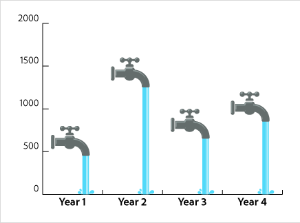
You can use graph designs to add illustrations to columns and markers. Graph designs can be simple drawings, logos, or other symbols representing values in a graph; they can also be complex objects that contain patterns and guide objects. Illustrator comes with a variety of preset graph designs. In addition, you can create new graph designs and store them in the Graph Design dialog box.
You can apply graph design to columns in several ways:
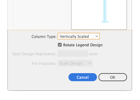
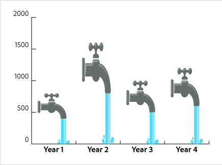
Vertically scaled design
Is stretched or compressed vertically. Its width does not change.
|
|
|
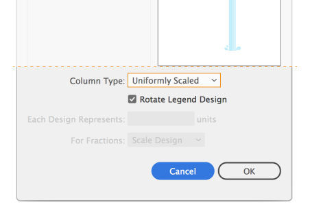
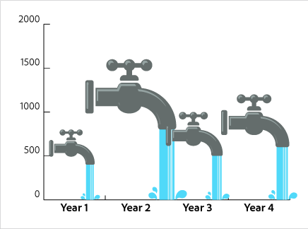
Uniformly scaled design
Is scaled both vertically and horizontally. The horizontal spacing of the designs is not adjusted for the different widths.
|
|
|
Repeating design
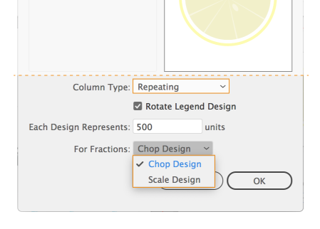
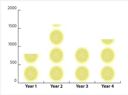
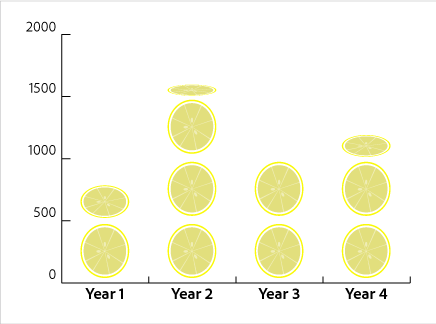
Stacks a design to fill the columns. You can specify the value that each design represents, as well as whether you want to chop or scale designs that represent fractions.
|
|
|
|
|---|---|---|
|
|
Example: Chop Design |
Example: Scale Design |
Sliding design
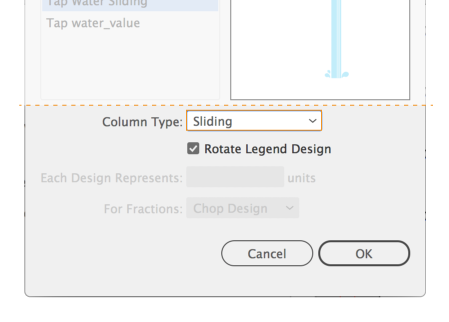
Is similar to a vertically scaled design, except that you can specify where in the design to stretch or compress it. For example, if you were using a person to represent data, you might stretch or compress only the body, but not the head. Using the Vertically Scaled option would scale the entire person.
|
|
|
|---|
Import a column or marker design
You can transfer the graph designs you create between documents.
-
Choose Window > Swatch Libraries > Other Library.
-
To import graph designs from another document, select the document, and click Open. Initially, all that appears is a new panel with colors, gradients, and patterns from the imported file. However, the imported graph designs will be available when you open the Graph Column or Graph Marker dialog box.
Create a column design
-
Create a rectangle as the backmost object in the design. The rectangle represents the boundary of the graph design.Note
Copy and paste the smallest column in your graph to use it as the bounding rectangle for your design.
-
Paint the rectangle as desired, or fill and stroke it with None so that it is invisible.
-
Create the design using any of the drawing tools, or position an existing design in front of the rectangle.
-
Using the Selection tool (
 ), select the entire design, including the rectangle.
 -
Choose Object > Group to group the design.
-
Choose Object > Graph > Design.
-
Click New Design. A preview of the selected design appears. Only the portion of the design that fits inside the backmost rectangle is visible, but the whole design appears when used in the graph.
-
Click Rename to name the design.
NoteCreating a graph design is similar to creating a pattern.
Create a sliding column design
-
Create a rectangle as the backmost object in the design. This rectangle is the boundary for the graph design.
-
Create the design using one of the drawing tools, or place an existing design in front of the rectangle.
-
Use the Pen tool to draw a horizontal line to define where the design is to be stretched or compressed.
-
Select all parts of the design, including the horizontal line.
-
Choose Object > Group to group the design.
-
Use the Direct Selection tool (
 ) or Group Selection tool (
 ) to select the horizontal line. Be sure to select only the horizontal line.
 -
Choose View > Guides > Make Guides.
-
Choose View > Guides > Lock Guides to remove the check mark next to Lock so you can unlock the guides. Move the design around to make sure that the guide moves with the design.
-
Use the Selection tool (
 ) to select the whole design.
 -
Choose Object > Graph > Design.
-
Click New Design. A preview of the selected design appears.
-
Click Rename to name the design.
Apply a column design to a graph
-
Create or import the column design.
-
Use the Group Selection tool (
 ) to select the columns or bars you want to fill with the design, or select the entire graph.
 -
Choose Object > Graph > Column.
-
Select a column design type.Note
If you choose Repeating Column Type, enter a value in the Each Design Represents text box. Alsoselect whether to chop or scale any fractions of the design from the For Fractions pop‑up menu. Chop Design cuts off a fraction of the top design as necessary; Scale Design scales the last design to fit in the column.
-
Select the design you want to use. A preview of the selected design appears.
-
Click OK.
Add totals to a column design
-
Create the column design.
-
Select the Type tool
 . Position
the pointer at a point where you want the value to appear, near
or in the rectangle that defines the design.
For example, you can place the value in, above, below, to the left, or to the right of the design.
-
Click and type a percent sign (%) followed by two digits from 0 to 9. The digits control how the data is displayed.
The first digit determines how many places appear before the decimal point. For example, if your total was 122, a digit of 3 would display 122. If you enter 0 for the first digit, the program adds the number of places necessary for the value.
The second digit determines how many places appear after the decimal point. Zeros are added as necessary, and values are rounded up or down as necessary. You can vary these numbers, depending on how many digits you need.
-
To change the type attributes, choose Window > Type > Character, specify the attributes you want, and close the panel.
-
To align the decimal points, choose Window > Type > Paragraph and click the Align Text Right button.
-
Using the Selection tool (
 ), select the entire design, including the rectangle and any type.
 -
Choose Object > Group to group the design.
-
Choose Object > Graph > Design.
-
Click New Design. You see a preview of the selected design.
-
Click Rename to name the design.
Create a marker design
-
Select and copy a marker rectangle from the graph, and paste it where you're going to create your design. This will be the backmost object in your graph design and will establish the size of the marker.
-
Make the marker artwork the size you want it to be in the graph, even if it’s larger than the marker rectangle you copied.
-
Once you’ve got the marker design the way you want it, select the design, choose Object > Graph > Design, and click New Design.
-
Click Rename to name the design.
Apply a marker design to a line or scatter graph
-
Create or import the column design.
-
Use the Group Selection tool (
 ) to select the markers and the legends in the graph that you want to replace with a design. Do not select any lines.
 -
Choose Object > Graph > Marker. Select a design, and click OK.
The design is scaled so that the backmost rectangle in the design is the same size as the default square marker on the line or scatter graph.
Reuse a graph design
You can reuse a graph design that you created and edit it to make a new design. If you have the original artwork, you can alter it and then rename the design using the Graph Design dialog box.
If you don’t have the original artwork defined as a graph design, you can retrieve the original by pasting the graph design into your artwork.
-
Choose Select > Deselect to deselect all of the artwork.
-
Choose Object > Graph > Design.
-
Select the graph design that you want to paste into your artwork, and click Paste Design.
-
Click OK. The graph design is pasted into your artwork. You can now edit it and define it as a new graph design.


