- Substance 3D home
- User guide
- Glossary
- Getting started
- Workspace
- Workspace
- Customizing your workspace
- Home screen
- Main toolbar
- Preferences
- Explorer
- Graph view
- Library
- Properties
- 2D view
- 3D view
- Dependency manager
- Resources
- Resources
- Importing, linking and new resources
- Bitmap resource
- Vector graphics (SVG) resource
- 3D scene resource
- AxF (Appearance eXchange Format)
- Font resource
- Warnings from dependencies
- Substance graphs
- Substance graphs
- Substance graph key concepts
- Creating a Substance graph
- Instances and subgraphs
- Graph parameters
- Manage parameters
- 'Visible if' expressions
- Inheritance in Substance graphs
- Output size
- Values in Substance graphs
- Publishing Substance 3D asset files (SBSAR)
- Exporting bitmaps
- Exporting PSD files
- Sample Substance graphs
- Warnings in Substance graphs
- Nodes reference for Substance graphs
- Nodes reference for Substance graphs
- Atomic nodes
- Node library
- Node library
- Texture generators
- Texture generators
- Noises
- Noises
- 3D Perlin noise
- 3D Perlin noise fractal
- 3D Ridged noise fractal
- 3D Simplex noise
- 3D Voronoi
- 3D Voronoi fractal
- 3D Worley noise
- Anisotropic noise
- Blue noise fast
- BnW spots 1
- BnW spots 2
- BnW spots 3
- Cells 1
- Cells 2
- Cells 3
- Cells 4
- Clouds 1
- Clouds 2
- Clouds 3
- Creased
- Crystal 1
- Crystal 2
- Directional noise 1
- Directional noise 2
- Directional noise 3
- Directional noise 4
- Directional scratches
- Dirt 1
- Dirt 2
- Dirt 3
- Dirt 4
- Dirt 5
- Dirt gradient
- Fluid
- Fractal sum 1
- Fractal sum 2
- Fractal sum 3
- Fractal sum 4
- Fractal sum base
- Fur 1
- Fur 2
- Fur 3
- Gaussian noise
- Gaussian spots 1
- Gaussian spots 2
- Grunge concrete
- Grunge Damas
- Grunge galvanic large
- Grunge galvanic small
- Grunge leaks
- Grunge leaky paint
- Grunge map 001
- Grunge map 002
- Grunge map 003
- Grunge map 004
- Grunge map 005
- Grunge map 006
- Grunge map 007
- Grunge map 008
- Grunge map 009
- Grunge map 010
- Grunge map 011
- Grunge map 012
- Grunge map 013
- Grunge map 014
- Grunge map 015
- Grunge rough dirty
- Grunge rust fine
- Grunge scratches dirty
- Grunge scratches fine
- Grunge scratches rough
- Grunge shavings
- Grunge splashes dusty
- Grunge spots
- Grunge spots dirty
- Liquid
- Messy fibers 1
- Messy fibers 2
- Messy fibers 3
- Microscope view
- Moisture noise 1
- Moisture noise 2
- Perlin noise
- Plasma
- Caustics
- Voronoi
- Voronoi fractal
- Waveform 1
- White noise
- White noise fast
- Patterns
- Patterns
- 3D linear gradient
- 3D volume mask
- Alveolus
- Arc pavement
- Brick 1
- Brick 2
- Brick generator
- Checker 1
- Cube 3D
- Cube 3D GBuffers
- Fibers 1
- Fibers 2
- Gaussian 1
- Gaussian 2
- Gradient axial
- Gradient axial reflected
- Gradient circular
- Gradient linear 1
- Gradient linear 2
- Gradient linear 3
- Gradient radial
- Height extrude
- Mesh 1
- Mesh 2
- Panorama shape
- Polygon 1
- Polygon 2
- Scratches generator
- Shape
- Shape extrude
- Shape mapper
- Shape splatter
- Shape splatter blend
- Shape splatter data extract
- Shape splatter to mask
- Splatter
- Splatter circular
- Star
- Starburst
- Stripes
- Tile generator
- Tile random
- Tile random 2
- Tile sampler
- Triangle grid
- Weave 1
- Weave 2
- Weave generator
- Filters
- Filters
- Adjustments
- Adjustments
- Apply color palette
- Auto levels
- Channel mixer
- Chrominance extract
- Clamp
- Color match
- Color to mask
- Contrast/Luminosity
- Convert to linear
- Convert to sRGB
- Create color palette (16)
- Grayscale conversion advanced
- Hald CLUT
- HDR range viewer
- Height map frequencies mapper
- Highpass
- Histogram compute
- Histogram equalize
- Histogram range
- Histogram render
- Histogram scan
- Non-uniform histogram scan
- Histogram select
- Histogram shift
- ID to mask grayscale
- Invert
- Lighting cancel high frequencies
- Lighting cancel low frequencies
- Luminance highpass
- Min max
- Modify color palette
- Pow
- Quantize color (Simple)
- Quantize color
- Quantize grayscale
- Replace color
- Replace color range
- Threshold
- View color palette
- Blending
- Blurs
- Channels
- Effects
- Effects
- 3D texture position
- 3D texture SDF
- 3D texture surface render
- 3D texture volume render
- Ambient occlusion (HBAO)
- Ambient occlusion (RTAO)
- Anisotropic Kuwahara color
- Anisotropic Kuwahara grayscale
- Bevel
- Bevel smooth
- Cross section
- Curvature
- Curvature smooth
- Curvature sobel
- Diffusion color
- Diffusion grayscale
- Diffusion UV
- Directional distance
- Edge detect
- Emboss with gloss
- Extend shape
- Flood fill
- Flood fill mapper
- Flood fill to Bbox size
- Flood Fill to gradient
- Flood Fill to grayscale/color
- Flood Fill to index
- Flood Fill to position
- Flood Fill to random color
- Flood Fill to random grayscale
- FXAA
- Glow
- Mosaic
- Multi directional warp
- Non-uniform directional warp
- Reaction diffusion fast
- RT irradiance
- RT shadow
- Shadows
- Shape drop shadow
- Shape glow
- Shape stroke
- Summed area table
- Swirl
- Uber emboss
- Vector morph
- Vector warp
- Normal map
- Tiling
- Transforms
- Material filters
- Material filters
- 1-click
- Effects (Material)
- Transforms (Material)
- Blending (Material)
- PBR utilities
- Scan processing
- Mesh-based generators
- Mesh-based generators
- Mask generators
- Weathering
- Utilities (Mesh-based generators)
- Spline & Path tools
- Spline & Path tools
- Working with Path & Spline tools
- Paths to spline
- Path tools
- Spline tools
- Spline tools
- Point list
- Scatter on Spline color
- Scatter on Spline grayscale
- Scatter Splines on Splines
- Spline 2D transform
- Spline (Cubic)
- Spline (Poly quadratic)
- Spline (Quadratic)
- Spline append
- Spline bridge (2 Splines)
- Spline bridge (List)
- Spline bridge mapper color
- Spline bridge mapper grayscale
- Spline circle
- Spline fill
- Spline flow mapper
- Spline mapper color
- Spline mapper grayscale
- Spline merge list
- Spline render
- Spline sample height
- Spline sample thickness
- Spline select
- Spline warp
- UV mapper color
- UV mapper grayscale
- 3D view (Library)
- 3D view (Library)
- HDRI tools
- Node library
- Substance function graphs
- Substance function graphs
- What is a Substance function graph?
- Create and edit a function
- The Substance function graph
- Variables
- FX-maps
- FX-Maps
- How it works
- The Iterate node
- The Quadrant node
- Using Substance function graphs in FX-Maps
- Warnings in Substance function graphs
- Sample Substance function graphs
- Nodes reference for Substance function graphs
- Nodes reference for Substance function graphs
- Function nodes overview
- Atomic function nodes
- Function node library
- MDL graphs
- Working with 3D scenes
- Bakers
- Best practices
- Pipeline and project configuration
- Color management
- Package metadata
- Scripting
- Scripting
- Plugin basics
- Plugin search paths
- Plugins packages
- Plugin manager
- Python editor
- Accessing graphs and selections
- Nodes and properties
- Undo and redo
- Application callbacks
- Creating user interface elements
- Adding actions to the Explorer toolbar
- Using color management
- Using spot colors
- Logging
- Using threads
- Debugging plugins using Visual Studio Code
- Porting previous plugins
- Packaging plugins
- Scripting API reference
- Technical issues
- Release notes
In: Spline & Path Tools > Spline Tools
Description
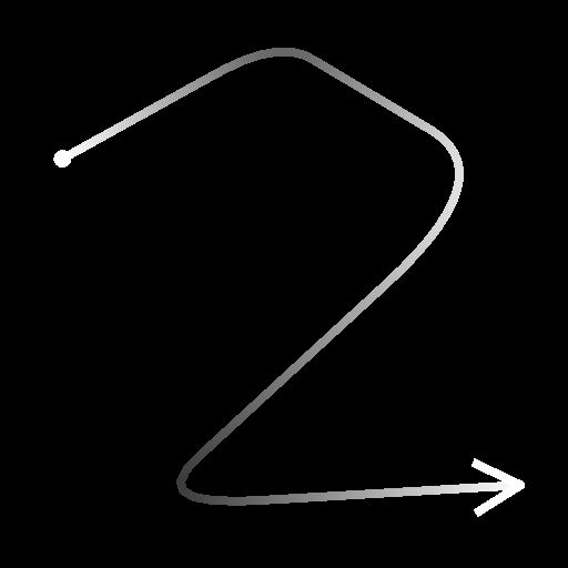
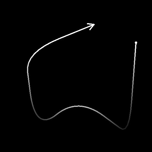
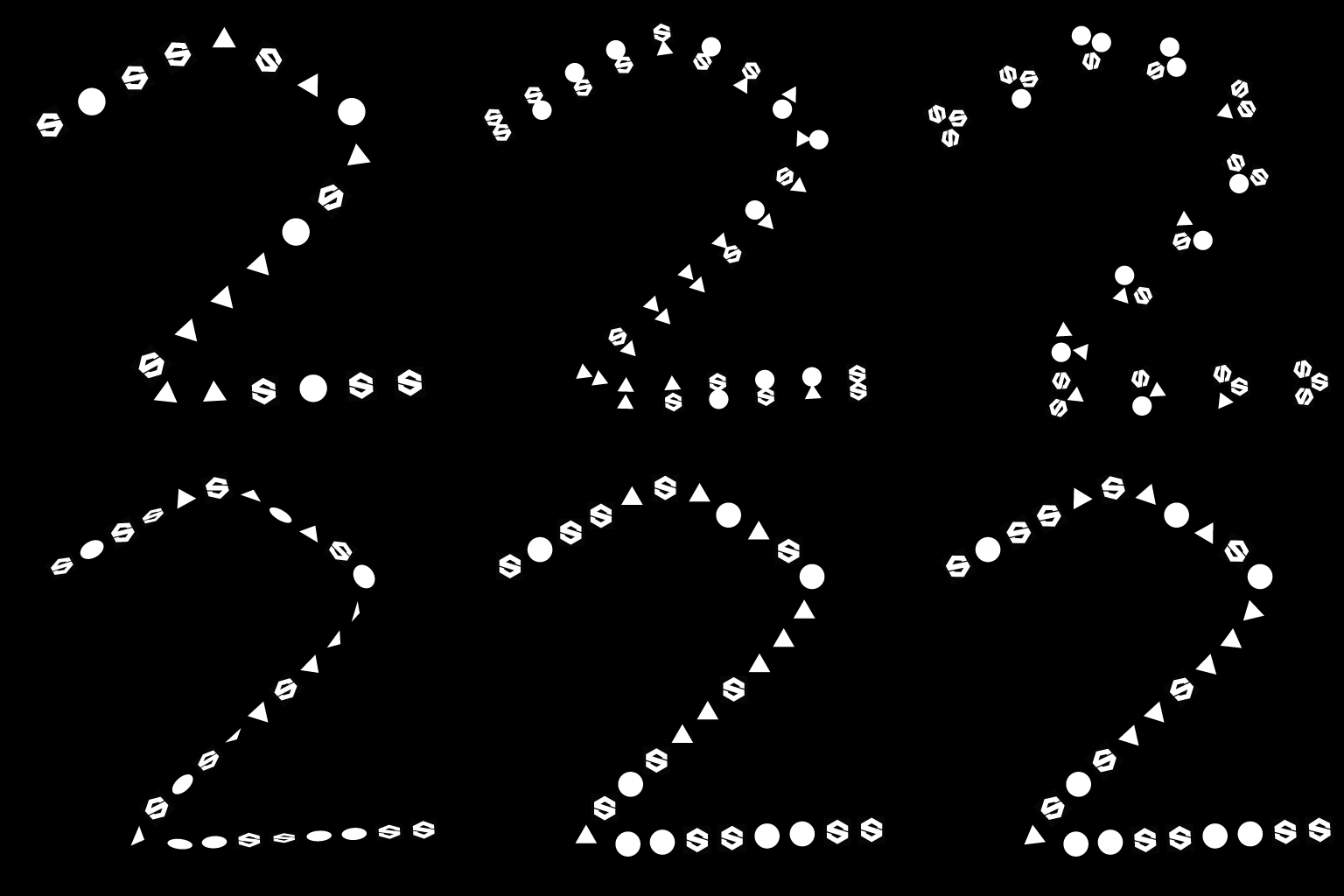
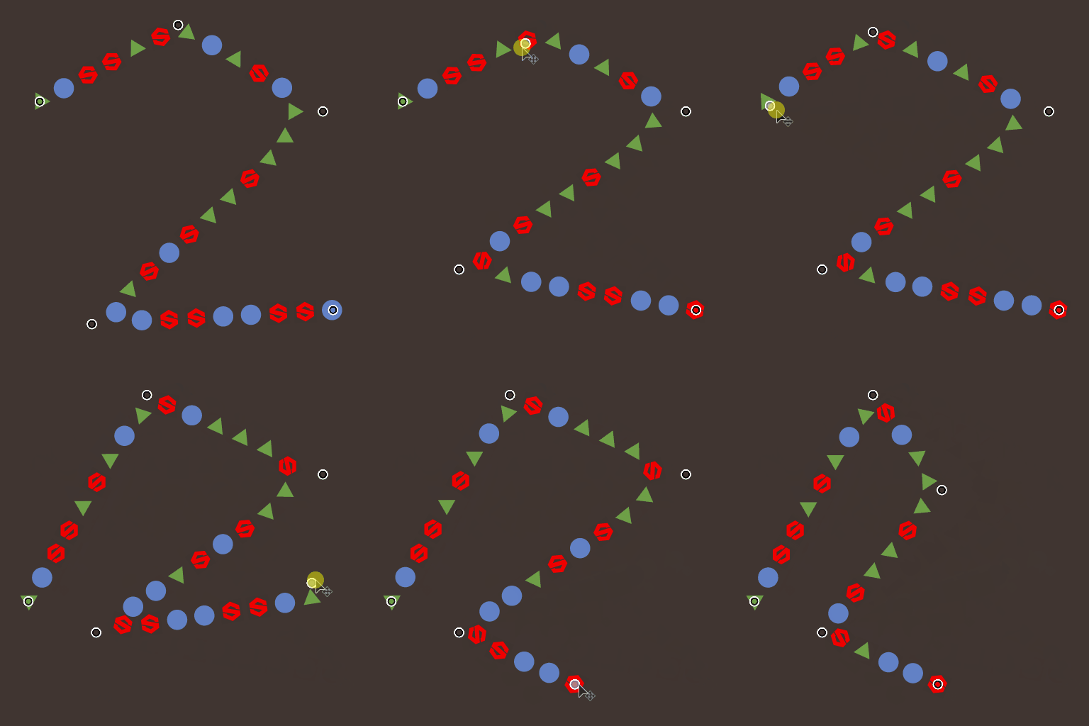
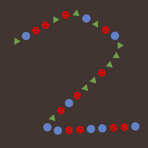
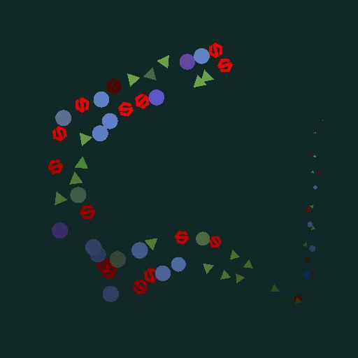
Draws the specified pattern(s) along the input splines over the input background.
The node offers deep customization options for controlling how patterns are scattered
Some aspects of the scattering may be controlled using images from other nodes in the graph to further the dynamic aspect of the result.
See also Scatter on Spline Grayscale.
Input connectors
Background Grayscale (Primary)
The grayscale image over which splines should be drawn.
Spline Coords Color
The coordinates of the input splines’ points encoded in the RGBA channels of a color image:
R - X position
G - Y position
B - Height
A - Packed data:
- Sign: Spline is closed (negative) or open (positive);
- Absolute value: Thickness + 1.
Spline Data Color
Additional data of the input splines encoded in the RGBA channels of a color image.
R - Tangents X
G - Tangents Y
B - Unused
A - Unused
Spline Amount Integer
The number of input splines.
Pattern Input # Grayscale
The pattern(s) which should be scattered along the splines.
Scale Map Grayscale
The map controlling the scale of the scattered patterns. The effect of this map is controlled by the ‘Scale Map Input Multiplier’ parameter and is combined with the other parameters in the ‘Size’ group.
Height Map Grayscale
The map controlling the height of the scattered patterns. The effect of this map is controlled by the ‘Height Input Multiplier’ parameter and is combined with the other ‘Color’ parameters in the ‘Color’ group.
Mask Map Grayscale
The map controlling the masking of the scattered patterns. The effect of this map is controlled by the ‘Mask Map Threshold’ parameter and is combined with the other ‘Mask’ parameters in the ‘Color’ group.
Output connectors
Output Grayscale
The image representing the pattern(s) scattered along the input spline(s) over the input background.
Parameters
Spline Input Integer
The method of selecting which splines should be used for scattering patterns:
- All splines: Use all splines in the input list;
- Single Spline: Use only the specified spline from the input list;
- Spline Range: Use only the splines in the specified range from the input list.
Spline Index Integer (Available when ‘Spline Input’ is set to ‘Single Spline’)
The list index of the spline which should be used for scattering patterns.
Spline Range Integer2 (Available when ‘Spline Input’ is set to ‘Spline Range’)
The range of list indexes including the splines which should be used for scattering patterns.
Scatter Mode Integer
The method of scattering the patterns along the splines, which impacts the amount of patterns on each spline:
- Shape Amount: The specified amount of evenly spaced patterns is scattered;
- Shape Spacing: The number of patterns is automatically adjusted to fit the specified even spacing.
In both cases, the first and last patterns fall exactly on the start and end of each spline respectively.
Shape Amount Integer (Available when ‘Scatter Mode’ is set to ‘Shape Amount’)
The amount of evenly spaced patterns scattered along each spline.
Shape Distribution Along Spline Integer (Available when ‘Scatter Mode’ is set to ‘Shape Amount’)
The method of distributing the patterns along a spline:
- From Source: The spacing of the patterns is influenced by the spline point’s tangents, where shapes are further apart near points with long tangents;
- Uniform: The patterns are evenly spaced along the spline regardless of its tangents and trajectory.
Shape Spacing Float (Available when ‘Scatter Mode’ is set to ‘Shape Spacing’)
The minimum distance along a spline by which patterns should be spaced, while still landing the first and last pattern on the start and end of each spline respectively.
Start Float
Offsets the point from the start of a spline where the scattering starts. The value is the normalized length of each spline.
End Float
Offsets the point from the start of a spline where the scattering ends. The value is the normalized length of each spline.
Shape Pivot Float2
Offsets the pivot of the pattern X and Y in spline tangent space.
Considering the pivot is what is placed on the spline, this effectively offsets the patterns along or perpendicularly to the spline.
Note: The positions of the pivots impacts the effect of the ‘Scale’ and ‘Rotation (Pivot)’ parameters.
Pattern Integer
The pattern which should be scattered along the splines:
- Pattern Input: Use the patterns supplied to the ‘Pattern Input #’ inputs;
- Square;
- Disc;
- Paraboloid;
- Bell;
- Gaussian;
- Thorn;
- Pyramid;
- Brick;
- Gradation;
- Waves;
- Half Bell;
- Ridged Bell;
- Crescent;
- Capsule;
- Cone;
- Gradation w. offset;
- Hemisphere.
Pattern Input Number Integer (Available when ‘Pattern’ is set to ‘Pattern Input’)
Selects the index of the input pattern which should be scattered.
Pattern Input Distribution Integer (Available when ‘Pattern’ is set to ‘Pattern Input’)
The method used to select which of the input patterns should be scattered on a given spline:
- Random: a pattern is randomly selected;
- Along Spline: The pattern index increases gradually along the spline;
- Pattern Index: Loops over the index of input patterns along each spline;
- Spline Index: Loops over the index of input patterns from one spline to the next in the list of input splines.
Distribution Jittering Float (Available when ‘Pattern Input Distribution’ is set to ‘Along Spline’)
Randomly increases or decreases the selected index of patterns on the spline.
Override First Pattern Boolean
Manually select the index of the pattern that should be placed at the start of each spline.
First Pattern Input Index Integer (Available when ‘Override First Pattern’ is set to ‘True’)
The index of the pattern that should be placed at the start of each spline.
Override Last Pattern Boolean
Manually select the index of the pattern that should be placed at the end of each spline.
Last Pattern Input Index Integer (Available when ‘Override Last Pattern’ is set to ‘True’)
The index of the pattern that should be placed at the end of each spline.
Distribution Mode Integer
The method used to place the duplicate patterns:
- Linear: duplicates are evenly spaced along the spline’s normal from the pattern’s original location;
- Circular: duplicated are arranged along a virtual circle centered on the spline at the pattern’s original location.
Duplicates Amount Integer
The number of duplicated patterns.
Offset Float2 (Available when ‘Distribution Mode’ is set to ‘Linear’)
Applies an offset to the duplicates’ positions along the spline’s tangent (parallel) and normal (perpendicular).
Duplicates on opposite sides of the spline are moved in opposite directions.
Offset Center Float2 (Available when ‘Distribution Mode’ is set to ‘Linear’)
Applies an offset to the duplicates along the spline on X (parallel) and Y (perpendicular).
Spread Angle Float (Available when ‘Distribution Mode’ is set to ‘Circular’)
The arc of the virtual circle along which duplicates are distributed, as the angle of that arc where 1 is the full circle.
Offset Distance Float (Available when ‘Distribution Mode’ is set to ‘Circular’)
The radius of the virtual circle along which duplicates are distributed.
Rotation Float
Rotates the virtual circle along which duplicates are distributed.
Offset Start/End Attenuation Float2
Factors in the distance from the midpoint of the spline to its Start and End, when applying offsets to duplicates.
This means offsets are decreased for duplicates closer to a spline’s extremities.
Offset Attenuation by Thickness Float
Factors in the spline’s thickness when applying offsets to duplicates.
This means offsets are decreased for duplicates on a portion of a spline with a lower thickness.
Size Mode Integer
The method of setting the size of the scattered patterns:
- Normal: Size is controlled uniformly using a global ‘Scale’ parameter;
- Use Thickness from Spline: Size is driven by the spline’s thickness.
Thickness Affects Integer (Available when ‘Size Mode’ is set to ‘Use Thickness from Spline’)
Specifies which axis of a pattern’s scale should be driven by the spline’s thickness:
- X & Y: Thickness is multiplied against the size in both the X and Y axes;
- X: Thickness is multiplied against the size on the X axis only;
- Y: Thickness is multiplied against the size on the Y axis only.
When not multiplied, the pattern’s original scale is the full span of the image.
This means in the ‘X’ mode, the size in the Y axis is the full span of the image and needs to be tweaked using the Size parameter. The same applied for size in the X axis when using the ‘Y’ mode.
Size Float2
The original size of patterns in X and Y before other adjustments are made by other parameters.
Size Random Float2
Applies a random multiplier up to the specified value for reducing the size of the patterns in X and Y.
Thickness Scale Float (Available when ‘Size Mode’ is set to ‘Use Thickness from Spline’)
An additional multiplier for the scale of the patterns when driven by the spline’s thickness.
Scale Float (Available when ‘Size Mode’ is set to ‘Normal’)
A global control for the size of all patterns, where 1 is the full span of the image.
Scaling is applied relatively to a pattern’s pivot. The pivot position can be offset using the ‘Shape Pivot’ parameter.
Scale Random Float
Applies a random multiplier up to the specified value for decreasing the size of the patterns.
Scale Map Input Multiplier Float
Controls the intensity of the Scale Map input. This map acts as a multiplier for the current size of the patterns.
The effect of this map is combined with the other parameters in the ‘Size’ group.
Scale Input Sampling Mode Texture Space
The method of mapping the values in the Scale Map to the splines:
- Texture space: The values are applied to the splines where they would be if placed in a texture using the texture’s UV coordinates. This effectively applies the value to the splines ‘in place’;
- Horizontal along spline: The values are applied to the encoded splines’ coordinates directly (see Spline Coords input), where each row is applied to a different spline from top to bottom;
- Hor. along spline (rand. offset X): The values are applied to the encoded splines’ coordinates directly (see Spline Coords input), with a random horizontal offset in the Scale map for each spline (I.e., each row in Spline Coords);
- Hor. along spline (rand. offset Y): The values are applied to the encoded splines’ coordinates directly (see Spline Coords input), with a random vertical offset in the Scale map for each spline (I.e., each row in Spline Coords).
Start/End Attenuation Float2
Factors in the distance from the midpoint of the spline to its Start and End when scaling the patterns.
This means size is decreased for patterns closer to a spline’s extremities.
Local Offset Float2
Applies an offset to the patterns’ positions along the spline’s tangent (parallel) and normal (perpendicular).
Local Offset Random Float2
Applies an additional random offset to the patterns’ positions along the spline’s tangent (parallel) and normal (perpendicular).
Local Offset Random Center Float2
Offsets the center of the random offset applied by the Local Offset Random parameter along the spline’s tangent (parallel) and normal (perpendicular).
Local Offset Start/End Attenuation Float2
Factors in the distance from the midpoint of the spline to its Start and End when applying position offsets to the patterns.
This means offsets are decreased for patterns closer to a spline’s extremities.
Local Offset Attenuation by Thickness Float
Factors in the spline’s thickness when applying offsets to patterns.
This means offsets are decreased for duplicates on a portion of a spline with a lower thickness.
Offset on Spline Float
Applies a position offset to the patterns along the splines.
Random Offset on Spline Float
Applies an additional position offset to the patterns along the splines.
Align with Tangent Boolean
Rotates the patterns to match the direction of the spline at their location.
Rotation (Pivot) Float
Rotates the patterns around their pivots.
The pivot position can be offset using the ‘Shape Pivot’ parameter.
Rotation Random (Pivot) Float
Applies an additional random rotation to the patterns around their pivots.
The pivot position can be offset using the ‘Shape Pivot’ parameter.
Rotation Random Center (Pivot) Float
Rotates around the pattern’s pivots the center of the random rotations applied by the Rotation Random parameter.
Rotation (Center) Float
Rotates the patterns around their center.
Rotation Random (Center) Float
Applies an additional random rotation to the patterns around their center.
Rotation Random Center (Center) Float
Rotates around the pattern’s center the center of the random rotations applied by the Rotation Random parameter.
Background Color Float4
The color of the background in the output image.
Blend Mode Integer
The method of blending together the colors of patterns with both the background and other overlapping patterns:
- Add: Add the colors together;
- Alpha Blend: Applies a simple transparency blending using the pattern's alpha channel. Patterns drawn last are in front.
Color Mode Integer
The method of blending selecting the color of each pattern:
- Base Color: The Base Color is applied to all patterns;
- Position: The position of the pattern in texture space is used to drive its color so that the X and Y coordinates are mapped to the red and green channels respectively.
Shape Base Color Float4
The base color of the patterns.
Color Input Multiplier Float
Controls the intensity of the Color Map input. This map acts as a multiplier for the current color of the patterns.
The effect of this map is combined with the other parameters in the ‘Color’ group.
Note: The output color is the weighted result of all color multipliers.
Color Map Input Sampling Mode Integer
The method of mapping the values in the Color Map to the splines:
- Texture space: The values are applied to the splines where they would be if placed in a texture using the texture’s UV coordinates. This effectively applies the value to the splines ‘in place’;
- Horizontal along spline: The values are applied to the encoded splines’ coordinates directly (see Spline Coords input), where each row is applied to a different spline from top to bottom;
- Hor. along spline (rand. offset X): The values are applied to the encoded splines’ coordinates directly (see Spline Coords input), with a random horizontal offset in the Color Map for each spline (I.e., each row in Spline Coords);
- Hor. along spline (rand. offset Y): The values are applied to the encoded splines’ coordinates directly (see Spline Coords input), with a random vertical offset in the Color Map for each spline (I.e., each row in Spline Coords).
Random Color Float4
Applies a random offset up to the specified values to the patterns’ colors in HSV space, as well as their alpha.
Note: The output color is the weighted result of all color multipliers.
Random Color Center Float
Applies an offset to the range of the random offset applied in Random Color
A value of -1 means all random values are higher and a value of 1 means all random values are lower.
Spline Thickness Multiplier Float
The intensity by which the color of each pattern is multiplied against the thickness of the spline at its location.
Note: The output color is the weighted result of all color multipliers.
Shape Scale Multiplier Float
The intensity by which the color of each pattern is multiplied against its scale.
Note: The output color is the weighted result of all color multipliers.
Shape Index Multiplier Float
The intensity by which the color of each pattern is multiplied against its normalized index.
Note: The output color is the weighted result of all color multipliers.
Spline Height Multiplier Float
The intensity by which the color of each pattern is multiplied against the height of the spline at its location.
Note: The output color is the weighted result of all color multipliers.
Random Luminance Float
Applies a random multiplier up to the specified value for decreasing the luminance of the patterns.
Note: The output color is the weighted result of all color multipliers.
Spline Thickness Multiplier Float
The intensity by which the alpha of each pattern is multiplied against the thickness of the spline at its location.
Note: The output color is the weighted result of all color multipliers.
Shape Scale Multiplier Float
The intensity by which the alpha of each pattern is multiplied against its scale.
Note: The output color is the weighted result of all color multipliers.
Shape Index Multiplier Float
The intensity by which the alpha of each pattern is multiplied against its normalized index.
Note: The output color is the weighted result of all color multipliers.
Spline Height Multiplier Float
The intensity by which the alpha of each pattern is multiplied against the height of the spline at its location.
Note: The output color is the weighted result of all color multipliers.
Random Luminance Float
Applies a random multiplier up to the specified value for decreasing the alpha of the patterns.
Note: The output color is the weighted result of all color multipliers.
Mask Random Float
Adjusts the range of the random masking of patterns, where 0 means no patterns are masked and 1 means all patterns are.
Mask Map Threshold Float
Values in the Mask Map below this threshold value are processed as black, while values above the threshold are processed as white.
This means all patterns in areas of the Mask Map below this value will be masked.
Mask Map Input Sampling Mode Integer
The method of mapping the values in the Mask Map to the splines:
- Texture space: The values are applied to the splines where they would be if placed in a texture using the texture’s UV coordinates. This effectively applies the value to the splines ‘in place’;
- Horizontal along spline: The values are applied to the encoded splines’ coordinates directly (see Spline Coords input), where each row is applied to a different spline from top to bottom;
- Hor. along spline (rand. offset X): The values are applied to the encoded splines’ coordinates directly (see Spline Coords input), with a random horizontal offset in the Scale map for each spline (I.e., each row in Spline Coords);
- Hor. along spline (rand. offset Y): The values are applied to the encoded splines’ coordinates directly (see Spline Coords input), with a random vertical offset in the Scale map for each spline (I.e., each row in Spline Coords).
Invert Mask Map Boolean
Inverts the values of the Mask Map using a ‘One minus’ operation (1 - x).
Mask Invert Boolean
Inverts the masking of the patterns.
Non-Square Correction Boolean
Adjust the points’ positions to retain the spline shape in non-square resolutions.
Examples
